Header Graphic
     Design Test for Insulated Hand Tools to conform to ASTM F1505-01
     All tests will be carried out in an environment of 23 +/- 5 C humidity 45 to 75%
Test for Dielectric Strength


Test 1:  Test for Dielectric Strength

Test for Dielectric Strength S.I.P. Insulated Tools are safety tested to 10,000v ac.  All tools are safety marked "Double Diamond".  The tools are approved for 1000v ac, which provides a 10 - fold margin of safety.

Test for Impact Strength Ambient/Cold Temperature


Test 2:  Test for Impact Strength Ambient/Cold Temperature

a) Impact Test:  Ambient Temperature

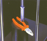
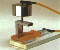
Carry out impact test in accordance with 5(a). (Pendulum apparatus) The hardness of the hammer shall be at least  20 HRC The tools are to be tested at the ambient temperature (23+/-5C) of the test room.

The fall height of the hammer is determined by the formula:

H=(w)/(P)=(2xF)/(P)

H= fall height of the hammer, m.

F= weight of the tool tested N

P= weight of the hammer N

W= energy

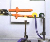
Determine the fall height H as a function of it's weight, P, so that the energy, w, of impact on the tool to be tested shall be equal to that of this tool falling from the height of 2m onto a hard surface. Three different locations will be impacted. The test is considered passed if no electrical punctures, spark over, or flashover occurs during the test period, and the limits of the leakage current are not exceeded.

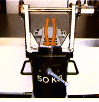
b) Impact Test:  Cold Temperature

Condition the tool by placement in a cooling chamber for 2 hours at -25+/-3C. The impact test shall take place within 2 minutes after removal from the cooling chamber. The ambient room temperature shall be 23+/-5C. The impact test should conform to the test in par. 2a. H=(w)/(p)=(0.6 x F)/P. Determine the fall height H as a function of it's weight, P so that the energy to that of the tool falling from a height of 0.6m on a hard surface.  

Insulation Resistance Testing

Test 3:  Insulation Resistance Testing

Immerse the tool with it's insulated part in a bath of tap water to a level of 24+2mm (1+1/16 in) from the nearest non-insulated part. The conductive part shall be above the water level.

Test pliers and similar tools in such a position that the gap between the two inner sides of the insulated handles is 2 to 3mm (1.16 to 1/8 in), or the minimum possible by the tools construction, but not less than 2mm (1/16 in).

After immersing in water for 24 hours continuously apply a voltage of 10kv at commercial power frequencies for 3 minutes and measure the leakage current. The current should be less than 1 m A for 200mm (8 in) of the coated tool.

Neither a spark over from the insulation to the bare plier head nor a breakdown through the insulation is acceptable.

Dielectric Testing (Indentation Test)

Test 4:  Dielectric Testing (Indentation Test)

No dielectric breakdown under pressure of 4.5 lbf at a temperature of 70 C (+158 F) at a test voltage of 5k V ac. Perform the test on insulated screwdriver blades at the middle of the insulated blade shank and on the other tools at the external middle part of the handles.

The probe should be a radius on the end and position the tool in so that the test point is in a horizontal position. At the end of the heating time and after the 5 minute cooling period outside the chamber, apply a voltage of 5kVrrms at commercial power frequencies continuously between the testing device and the conductive part of the tool for 3 minutes. The test is successful if no electrical puncture spark over or flash occurs during the test period.

Testing of Adhesiveness

Test 5:  Testing of Adhesiveness

The adhesion of the insulation material is tested to ensure firm bonding to the basic tool, for example on pliers at a tensile load of 375 lbf after being stored for 168 hours at 158 F.

According to the F1505-01 Standards, the test for pliers, strippers, cable cutting tools, cable scissors, and knives require only torque of 112.4 lbf (500 N) for 3 minutes.

The test is considered passed if the handle(s) remain firmly attached to the conductive part(s) and if the guard(s) remain firmly attached to the handle. Deformation of the insulation coating is not considered a failure.

Combustibility Test

Test 6:  Combustibility Test

The low flammability properties of our insulation material eliminates all risk of fire.

The flame resistance test is carried out in a draft-free room. The tool is clamped in a horizontal position. The burner nozzle is at a right angle to the middle part of the handle(s) of the tool. The fuel supply shall be technical grade methane gas with a suitable regulator and meter to produce a uniform gas flow.

At the start of the test, the tip of the testing flame should touch the insulating material at the lower part of the working head facing the sample.

The testing flame shall act upon the specimen for 10 seconds. After this period, withdraw the testing flame. Ensure that no air draft interferes with the test. Observe the propagation of the flame on the sample for 20 seconds after the withdrawal of the testing flame. The test is considered passed if the flame height, h, on the sample does not exceed 120mm (4-3/4 in.) during the 20 seconds of the observation period and there are no drops of melted material.